Designing and manufacturing active surfaces to exact specifications
Enormous time savings in the tryout phase
Because a large amount of time and effort is supposedly needed for design, active surfaces are often fully designed for only one side of the sheet metal (e.g. for the die). Offset dimensions (= sheet metal thickness) are then factored into the NC programs for NC manufacturing. Often stock allowances are also used in the NC programs to account for thinning effects and reliefs.
Although this procedure quickly yields an initial result, it also requires an enormous amount of manual effort in the spotting presses and usually in additional iterations in tryout.
Tebis offers automated design functions with which active surface designers can include sheet thickness, thinning effects and reliefs in the design of the CAD active surfaces. This results in realistic tool sets – accounting for all known and simulated forming effects. This enables time savings of hundreds of hours in NC programming, machining and tryout.
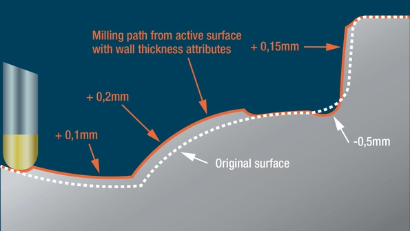
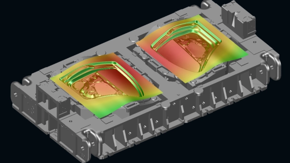
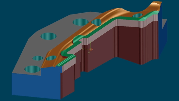
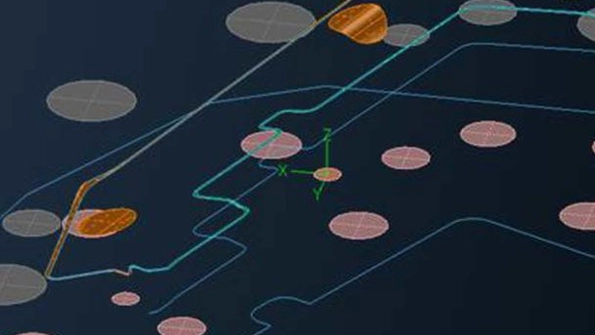
Usual method: Pressure surfaces (positive allowances) and reliefs (negative allowances) are not designed to meet exact specifications, but rather are milled in the active surfaces of the sheet metal die based on NC stock allowance attributes. The milled result (red surfaces) doesn’t correspond to the CAD model (dotted surface).
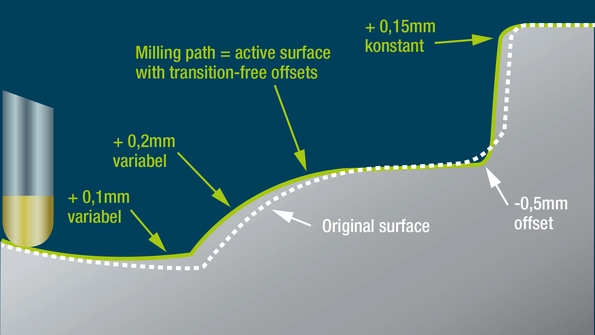
Tebis method: Pressure surfaces (positive allowances) and reliefs (negative allowances) are designed precisely and with transition areas in the CAD design (green surfaces). The CAD model is produced on the milling machine. The milled die components and the CAD model are identical.
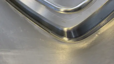
Usual method
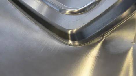
Visible edges in milled die surface
Usual method
Result after extensive grinding work
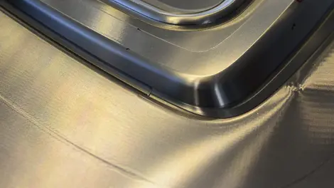
Tebis method
Die surface with no steps and without manual grinding work
- Reduced additional effort in design – Time invested in design pays for itself in manufacturing and tryout
- Fast and reliable manufacturing – Exact active surfaces are the prerequisite for NC automation and reliable simulation and for the use of high-feed cutters (HFC)
- Short manual tryout times – Finished die surfaces with no visible edges or transitions
Radii
For drawing operations: Relieve and flatten at the click of a button
For the die maker, relief means the reduction of rounded areas in concave areas of the matrix, punch, blank holder and all small parts, so as to ensure that the sheet metal in these areas is only contacted by one side of the die on forming.
This effect is achieved in convex active surface areas by flattening the radii.
Modify your active surfaces in the CAD design wherever possible. This lets you stabilize your overall process from the drawing simulation to the tryout press. Changes in rounded areas in the CAD design are quickly and precisely implemented in the die by means of NC programs and can be modified in a controlled manner to facilitate a stable process.
Tebis automatically detects radii and roundings and reduces the radii in the rounded areas at the click of a button, thereby creating tangential transitions to the adjacent surfaces.
The user interactively performs graphical modifications to convex roundings in the active surfaces in real time. The Tebis user determines the degree of the change with the control arrow.
Pressure surfaces and reliefs
For drawing operations: Fit areas together with smooth transitions
Pressure surfaces are required for large surface areas of the die in which the sheet metal must be held more securely during the drawing operation. Conversely, the sheet metal has greater freedom to stretch and expand, i.e. so that no pressure is exerted on the sheet metal. Free-form surfaces are designed for this purpose.
The video shows how Tebis automatically calculates positive and negative allowances for red areas. Green areas remain unchanged; orange areas are transition areas.
The before and after differences are rendered visible with a comparison function and can be measured by the user.
Outline surfaces
For trim operations: Automatically generate outline surfaces
For designing lower trim steels, the Tebis active surface designer creates outline surfaces with the click of a button. These surfaces already include the cutting gap and reliefs. A constant trim edge width is also included. The calculated surfaces are then used for the solid design of the lower part of the die.
Tip: You can also use the Tebis automatic small-part process for designing your trim steels.
Tebis automatically calculates outline surfaces (light areas) with reliefs (dark areas) from 2D and 3D curves.
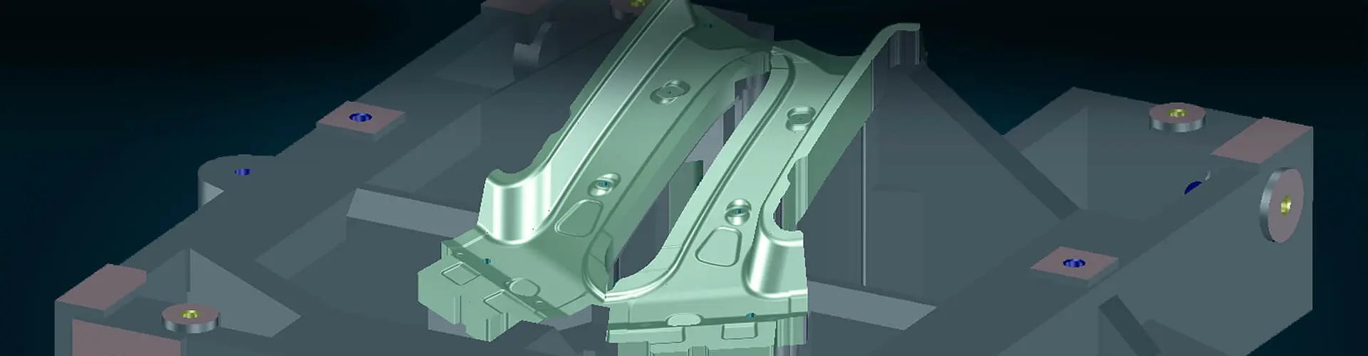
In the press, the sheet metal (green) is trimmed by the trim steel on the lower steel.
Theoretically designed trim edges
For trim operations: Precise results when trimming deep-drawing and bending parts
The “Create development curves” function can be used to quickly and easily determine theoretically designed trim edges for flanges on deep-drawing and bending parts. The material thickness of the component and the location of the neutral fiber are accounted for – and the result is highly precise, with no manual reworking necessary. The quality of the resulting curves corresponds to that of the original curves.
Multiple calculation modes cover different use cases.
Trim and coining steels
Automatically design small parts with all offsets, reliefs and bores
Trim steels are the small parts of a sheet metal die and can be designed and manufactured in a standardized and largely automated process. The Tebis automatic design process uses surface and solid geometry. It generates form and outline surfaces with offset and reliefs and cuts everything to exact solids with automatically generated extension and overrun surfaces.
The bores and fits required for securing the trim steel result from the assembly specification of the solid system. The cover surfaces needed to produce the trim steels by milling are created automatically.
The highly automated Tebis small-part process uses specifications from the solid design and the active surface design, enabling the user to easily generate precise and fully designed trim steels.
Bores and fits must first be closed to manufacture the trim steels on milling machines. Tebis automatically creates the cover surfaces.
Tebis uses bore features for all bores and fits, accessing the Tebis process library which is built up during process structuring. There are corresponding NC machining sequences for each bore feature, with information on tools and cutting data.
Press deflection
Designing compensation for gravitational forces
The upper sections of large-scale forming dies are subjected to gravitational forces that cause undesired defection of the die depending on the rigidity of the overall system. Tebis automatically and reliably compensates for this physical effect in the active surfaces. The Tebis morphing technology automatically morphs complex, free-form topologies to the specifications of an easily formulated morphing rule.
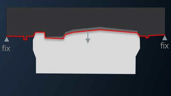
The die sags in the original state, with the result that the air gap to the punch is smaller in the center than around the outer area.