Using reverse engineering to align the CAD world with the real world
Create and update CAD surfaces with digitized data
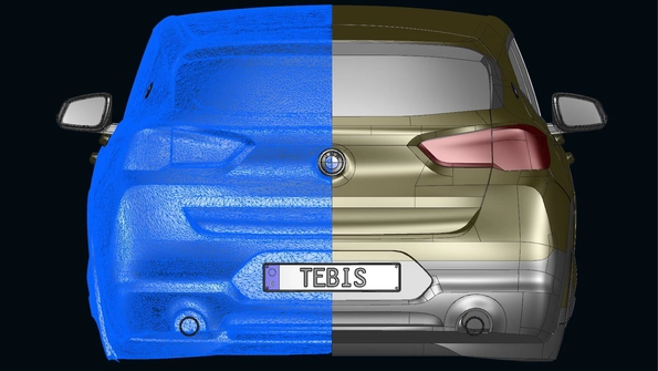
Reverse engineering generates a CAD surface model that precisely represents a scanned object. Reverse engineering is used everywhere where work is performed manually on real objects and a CAD model is required for the subsequent process.
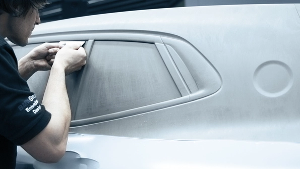
In model and mold manufacturing, design objects and vehicles modeled in clay are scanned and transferred to CAD surfaces.
In die manufacturing, manual changes to sheet-metal dies in the tryout phase are scanned The existing CAD model is updated based on the scanned data. CAD surfaces often have to be created for dies for which no CAD data at all are available.
Manually formed or modified objects are imported to Tebis after scanning.
A journey through time
- The fast track to up-to-date CAD data – Quickly generate surfaces and quickly adapt to modifications
- High CAD surface quality – Immediate use of CAD surfaces in subsequent processes
- Reverse engineering and design in a single system – High degree of flexibility for designers
How does it work?
Surface design and reverse engineering in a single application
In the same CAD file, the Tebis designer analyzes and optimizes the quality of the digitized data and then creates a wire-frame model and then the surface model is created based on that. Using the practical curve and surface functions, the designer supplements the surfaces generated by reverse engineering Free-form surfaces can be quickly generated using Tebis surface technology – and in class-A quality.
The video shows an application from die manufacturing: No special knowledge is required to create CAD design data from scanned sheet-metal parts.
These are the steps for using reverse engineering to generate high-quality CAD surfaces:
- Import STL data
- Analyze and edit mesh data
- Draw wire-frame model on mesh data
- Generate individual surfaces in the wire-frame model
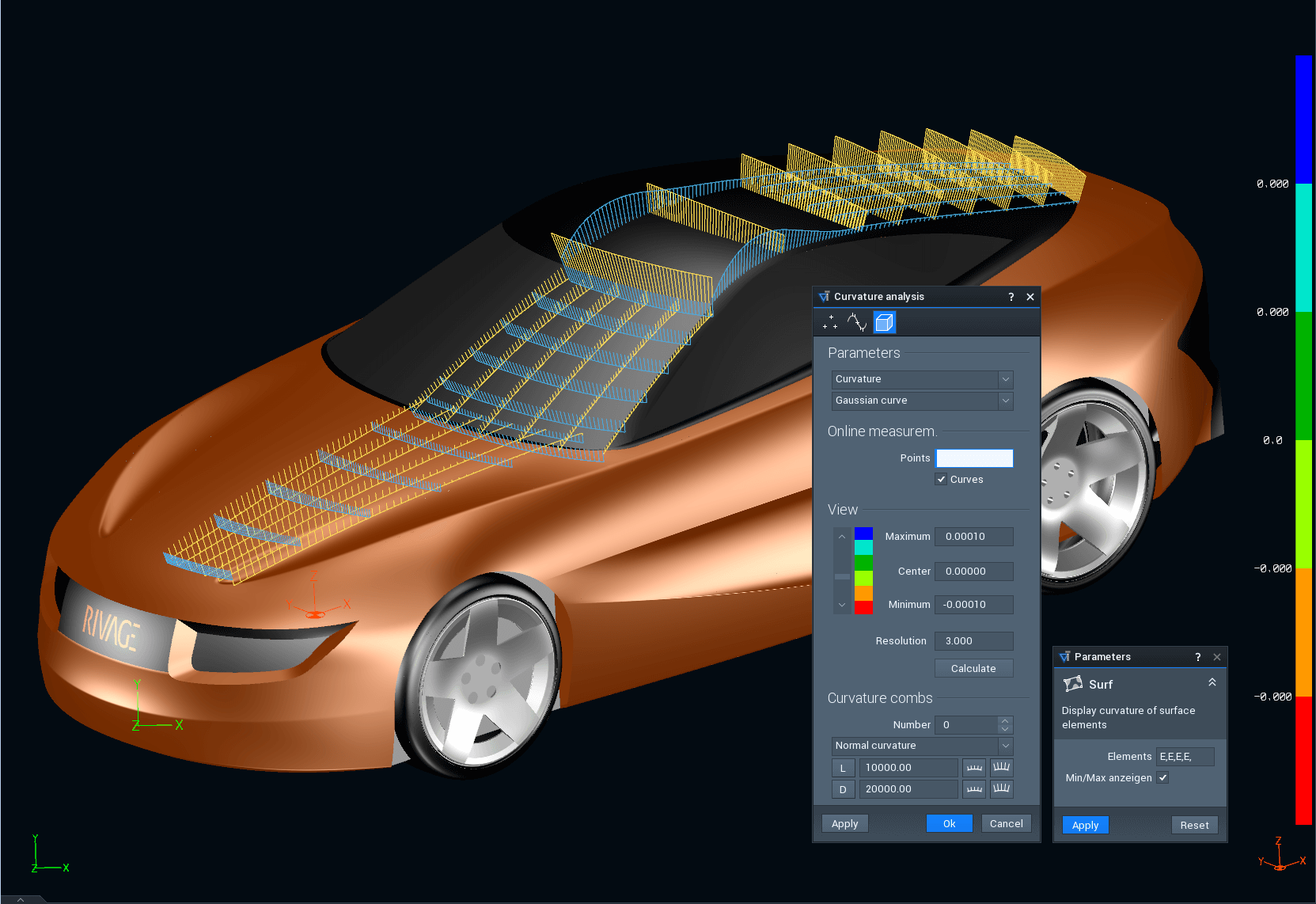
- Analyze surfaces
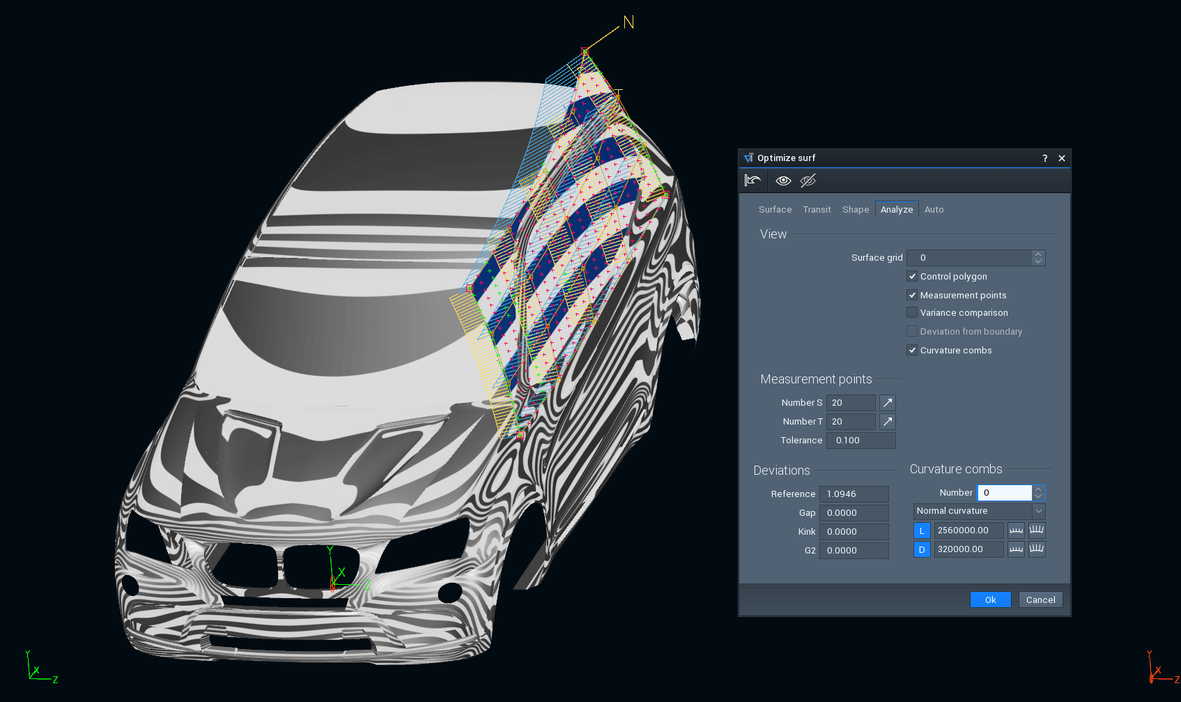
- Optimize surfaces
- Continue design work on the part
The video shows how easily the surface structures are drawn on the digitized data for the sheet-metal part, and how quickly a surface model with tangential free-form surfaces is created from that.
Always close to the mesh
Designing intuitively using the wire-frame and surface models
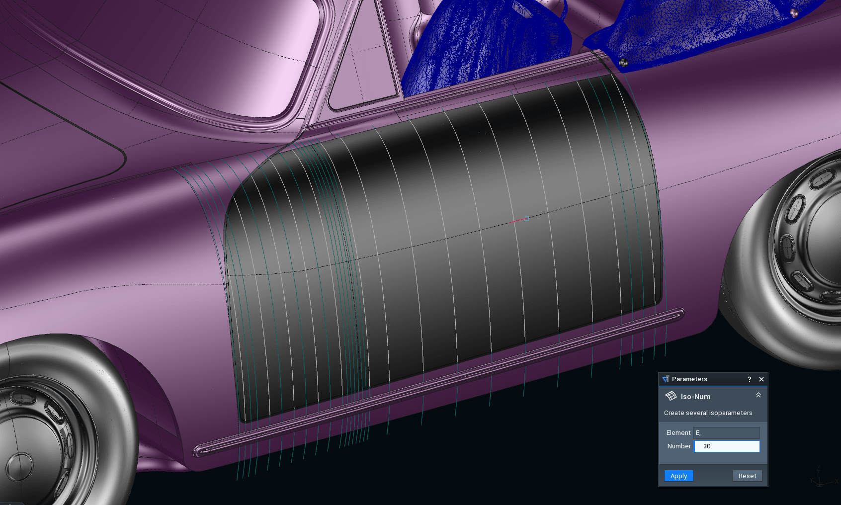
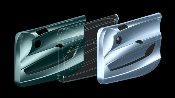
Using the semi-automatic and interactive drawing functions, users create an intelligent wire-frame model based on the scanned object (mesh model), on which the degree and segmentation of the surfaces and the quality of the surface transitions are automatically controlled. Using the wire-frame model, the user can define the layout of the surfaces and the qualities of the transitions to the adjacent surfaces. Tebis automatically calculates the surface model from the wire-frame model and the meshes. Using tolerance values, the user determines how tightly the wire-frame model and surfaces “adhere” to the digitized data.
Tebis offers convenient functions for generating the wire-frame model that are specially developed for working with stored meshes.
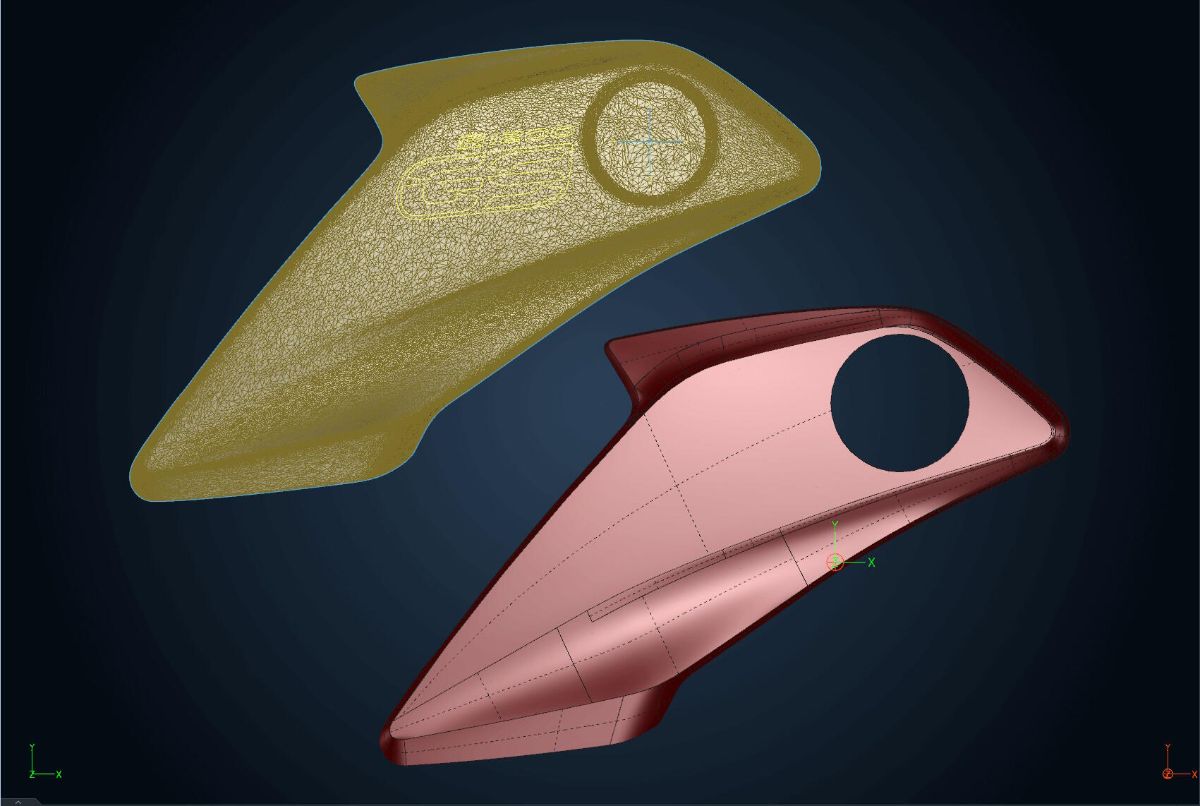
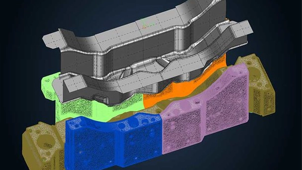
Tebis reverse engineering: from mesh (scan data) via wire-frame to surface model
Automatically from wire-frame to surface model: smoothing wire-frame model, fixing design curves, calculating surfaces and evaluating surface quality at a glance
More control of surface quality
Precisely adjust surface quality in transition areas
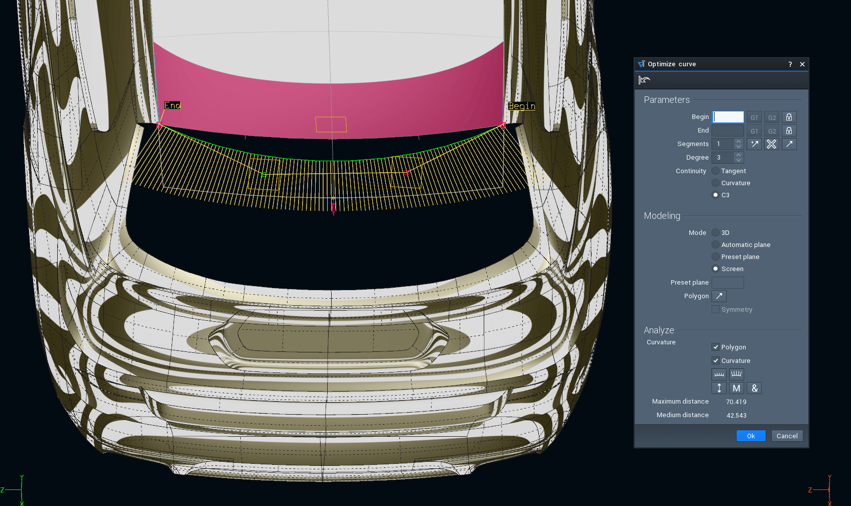
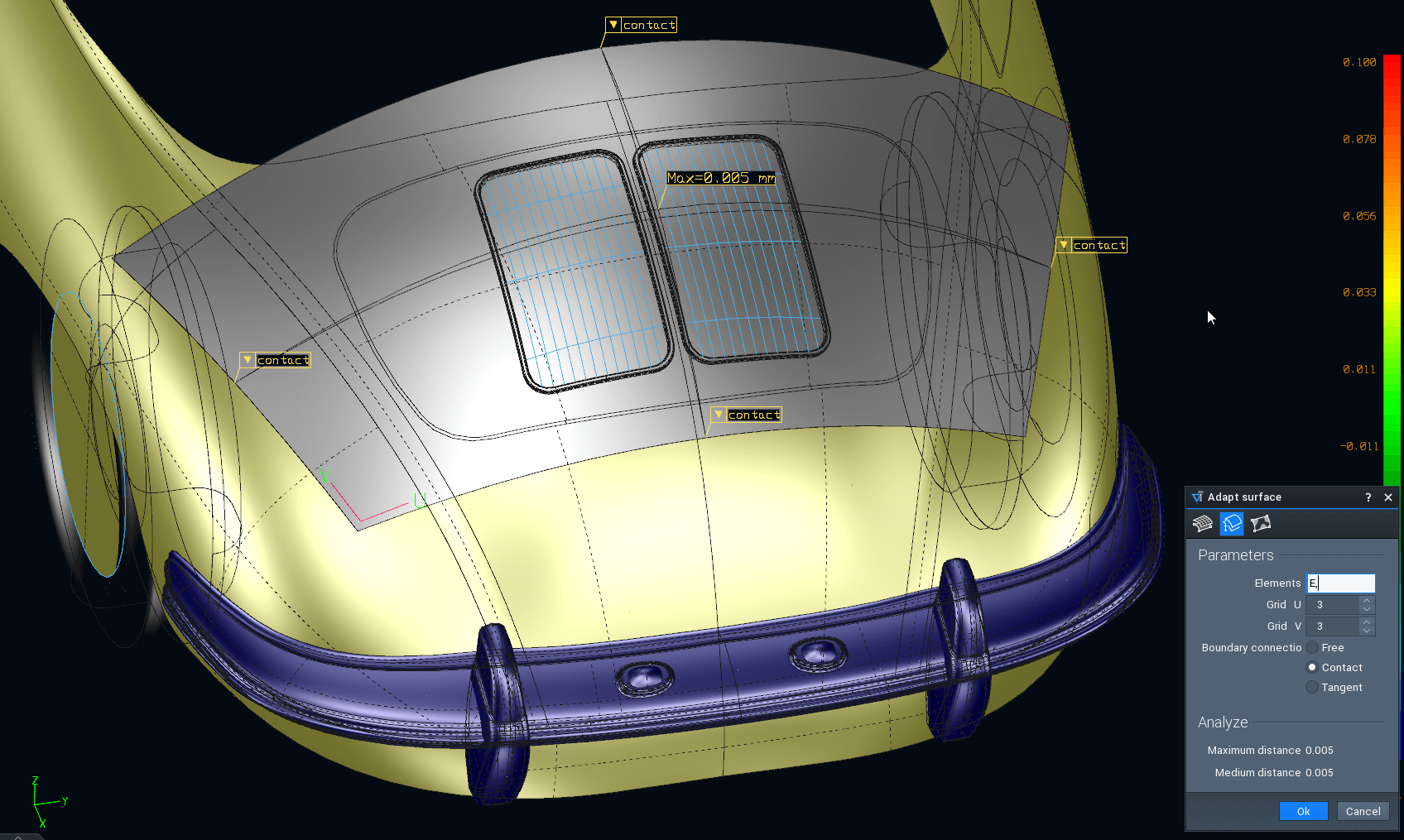
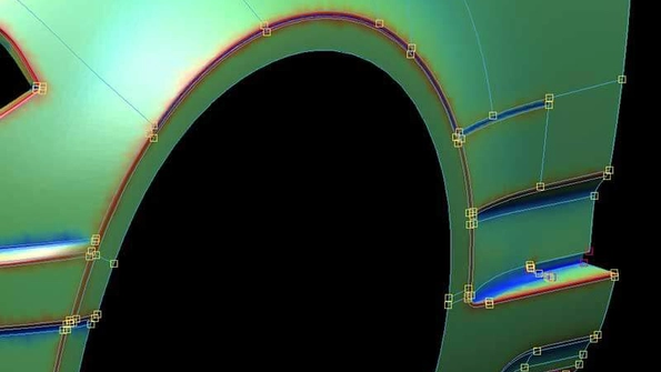
High-quality design surfaces require first-class CAD surface quality, especially for defined characteristic lines. Tebis enables precise control of the transition areas between two main surfaces or connecting surfaces (natural or trimmed surfaces), in addition to the basic surface approximation settings. The user specifies an area around the edge where the surface approximates the boundary curve rather than the scan data. The change in the CAD surface is immediately visible in Tebis. The affected area can be easily adjusted until the optimal surface quality is achieved.
Developed with BMW Group Design: Within the G0 loop radius, Tebis approximates the surface more to the boundary curve rather than to the scan data. The resulting surface can be easily and systematically optimized even for different part structures.
In die and mold manufacturing
For changes and missing die data
Reverse engineering in die manufacturing
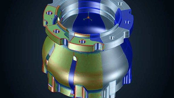
Tebis reverse engineering quickly generates virtual twins of real forming and injection molding dies. Existing CAD data can also be considered. In the following cases, reverse engineering is an extremely useful tool that yields significant time savings:
- Feedback of manual changes to the die from tryouts into the existing CAD model and ongoing work with a realistic, updated geometry
- Scanning a drawn sheet metal part and providing it as the surface model for subsequent operations (e.g. trimming) and fixtures
- Generating surfaces based on FEM meshes from simulation systems
- Production of a second die set, e.g. for additional production locations
- Repair after die breakage
Updating CAD surfaces on manual changes in the tryout
Die makers manually change dies in the tryout phase. This causes the CAD model to lose its validity. With reverse engineering, manual changes are scanned and conveniently imported into the CAD model file. This yields tremendous time savings for further optimization of the die and for duplicates.
The video demonstrates how the modified area in this reinforcing sheet is incorporated into the CAD model file.
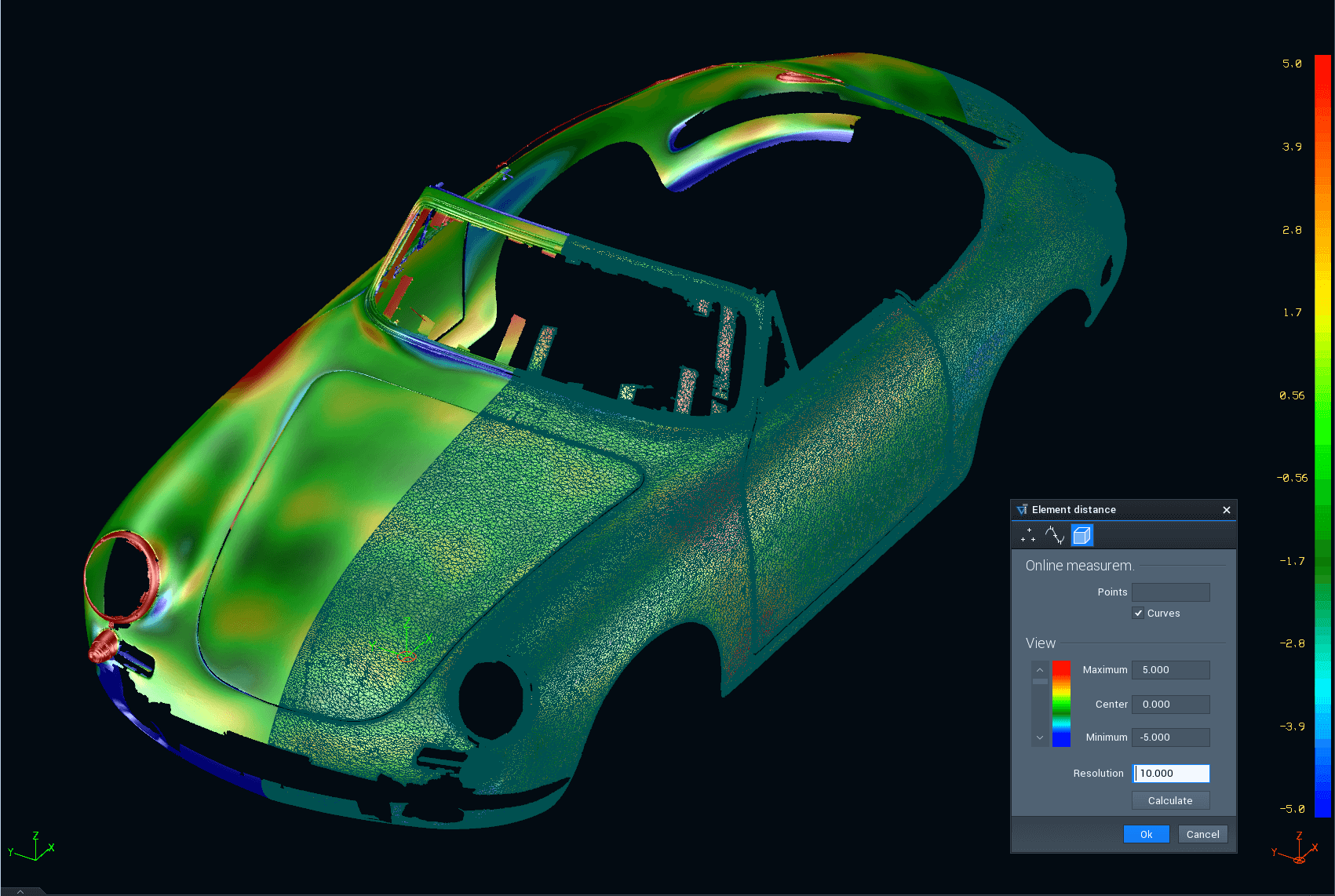
Tebis compares the CAD surfaces with the digitized data to detect where the die maker has made changes. The user updates the CAD surfaces in just a few minutes.
Reverse engineering based on simulation data
Mesh data from the drawing simulation can also be used as the basis for reverse engineering. First, the curvatures of the draw die system are analyzed. The designer then generates the surface layout and fills the individual areas with four-cornered surfaces and n-cornered surfaces trimmed as desired. Your method planners can very quickly obtain surface models in this way.
In design model making
For verification in form development
CAD surfaces are the starting point for all design and manufacturing processes after model making. If the form is developed by manual design methods like clay models or if the items are parts for antiques or art objects, the CAD world must simulate reality as precisely as possible.
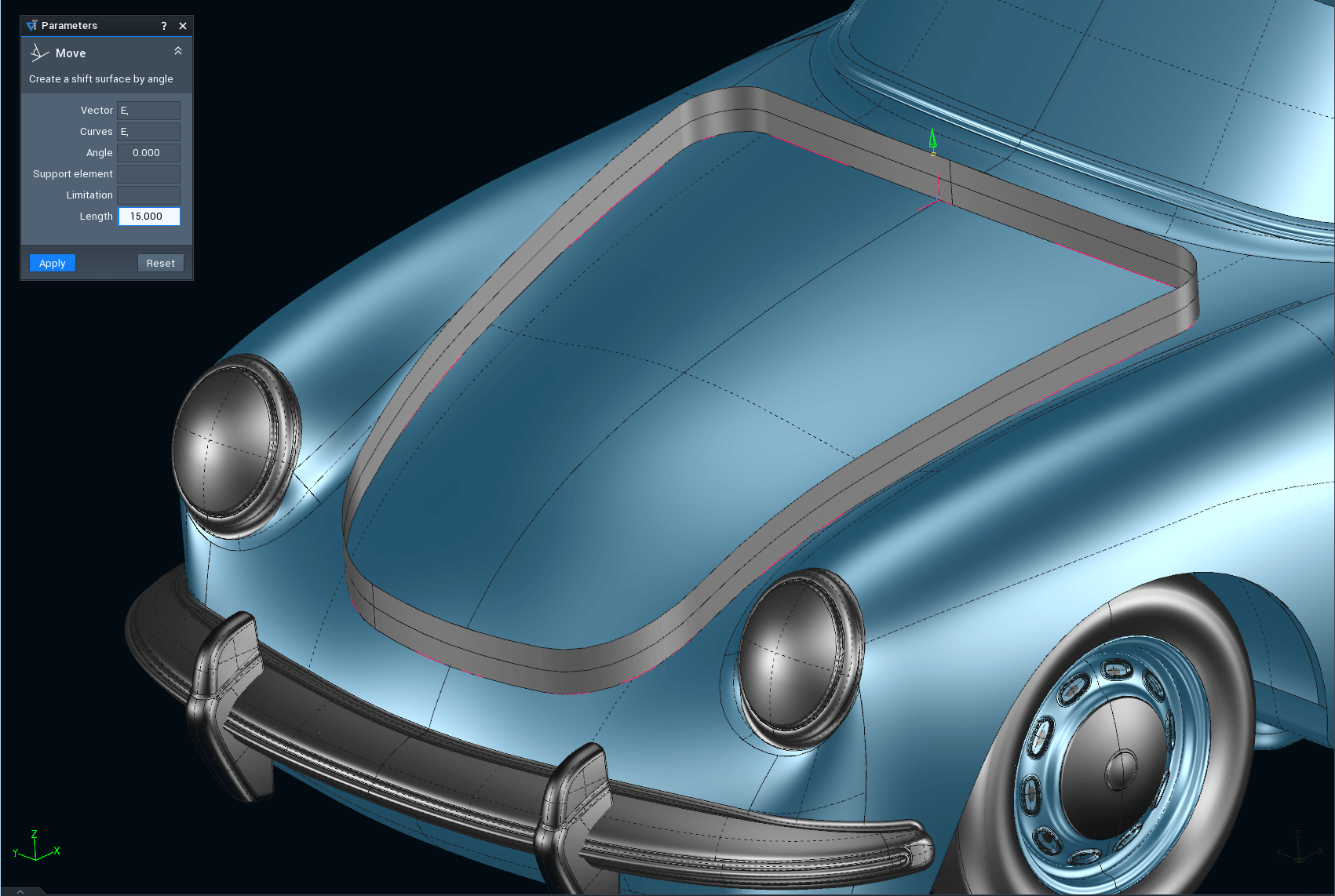
Model makers use reverse engineering to combine manual work and design technology and benefit from both worlds. You can create CAD surfaces for your physical models with very little effort. Learn more about the technical developments in cooperation with BMW Group Design. Reliable methods have been developed to combine form-finding via manual design as effectively as possible with virtual design.
Complete scope of functions for curves, meshes and surfaces